
Drainage Fields and Leach Field: How To Guide
All septic tanks must have a drainage field to treat the effluent further before it enters the ground water.
Many smaller package sewage treatment systems also discharge their effluent into a drainage field, primarily for liquid dispersal but also for additional effluent treatment.
The infiltration zone beneath the sub surface irrigation pipe becomes biologically active and enables additional treatment of the effluent. The unsaturated zone beneath this provides attenuation and a pathway for oxygen diffusion for further treatment. A saturated zone provides further dispersion and dilution of the treated effluent.
The siting and design of the drainage field depends on many factors,the most important of which is that there is sufficient suitable land with subsoil capable of absorbing the daily effluent discharge on a long term basis.
The UK regulators have issued documents which provide detailed guidance for planning an off mains system. DETR Circular 3/99 (this is the same as the Welsh Office circular 10/99) - planning requirements in respect of the use of Non-Mains Sewage requires that an independent assessment of the site and land is carried out before the installation of a sewage treatment plant. This can be carried out by our sister company RA Dalton. Your planning consent and agreement to discharge effluent requires this assessment.
BS 6297: 2007 is a new code of practice for the design and installation of drainage fields for use in wastewater treatment. It provides recommendations and guidance to aid preliminary planning, detailed site investigation to identify suitable drainage field locations and the assessment of site characteristics.
Site assessments must be made before equipment is purchased or installed as not all land is suitable for drainage field use. A percolation test establishes the length and area of infiltration trench required to disperse the effluent. Soil porosity can vary across a site and the percolation test should be carried out at the intended location of the proposed drainage field.
Other regulatory documents should be consulted, pollution prevention guideline no 4 (PPG4) and Building Regulations Part H (M in Scotland). However, please note that BS 6297:2007 provides the latest and most detailed percolation test method, a summary of which follows.
In order to assess the infiltration zone a percolation test is required. A deeper trial hole should be used to identify the soil and conditions beneath the drainage field, including the position of the seasonally highest water table. There should be a minimum of 1.2m of unsaturated soil above the position.
How to do a Step-By-Step Percolation Test
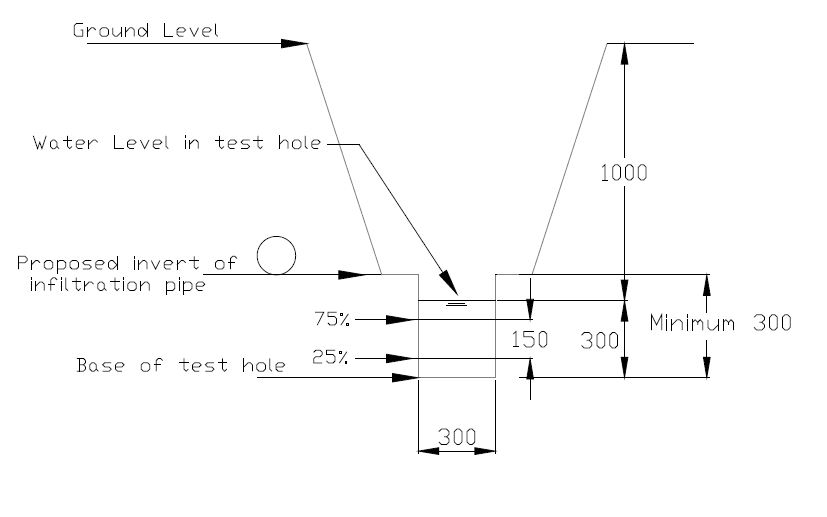
1. Excavate at least two holes, 300 mm square to a depth at least 300 mm below the proposed invert level (bottom of the infiltration pipe), spacing them along the proposed line of the subsurface irrigation system. While digging the hole, note and record changes in soil characteristics at measured depths and the position of the water table if reached
2.Saturate the local soil by filling each hole with water to a depth of at least 300 mm and allow this to seep away completely.
3. If the water drains rapidly, within 10 minutes, the hole should be refilled up to a maximum of 10 times. If the water continues to drain away rapidly, the ground is unsuitable.
4. If the water has not soaked away within 6 hours, the area is not suitable.
5. Determine the percolation rate by refilling each hole with water to a depth of at least 300 mm and observe the time
in seconds for the water to seep away from 75% full to 25% full (i.e. a depth of 150 mm).
6. Divide this time in seconds by 150. This gives the average time in seconds required for the water to drop 1 mm.
7. Repeat the test at least three times in each hole.
8. Take the average figure from the tests to produce the percolation value Vp (in seconds).
9. Obtain the average figure for the percolation value (Vp) by summing all the values and dividing by the number of
values used.
10. Retain the results, these may be required by the regulator and the property owner.
11. Where the Vp results vary widely (50% above or below the average figure), make further tests on a minimum of three different locations in the area of the proposed drainage field.
12. Drainage field disposal can only be used when percolation tests indicate average values of Vp between 15 and 100 and the preliminary assessment of the trial hole tests has been favourable
13. The minimum value of 15 ensures that untreated effluent cannot percolate too rapidly into the ground potentially resulting in the pollution of groundwater. Where Vp is above the limit of 100, effective treatment is unlikely to take place in the drainage field as there will be inefficient soakage leading to wastewater ponding on the surface.
14. If the Vp is between one and 15, or greater than 100, the regulator should be consulted to identify alternative options for disposal.
Calculating trench area and trench length
The Vp is used to determine the total floor area of the drainage trenches and therefore the total length of irrigation
drain. For domestic premises, the floor area of the drainage field required may be calculated as follows:
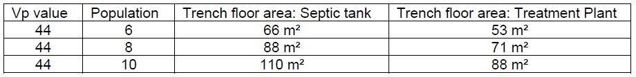
A = p x Vp x 0.25 for septic tanks
Or
A = p x Vp x 0.20 for package wastewater treatment plants (i.e. 20 % less, because the effluent has received additional treatment)
A= required drainage field floor area in square metres (m2).
P= number of people served by the tank (for domestic applications this should be the maximum number of people that could live in the dwelling).
Vp= percolation value.
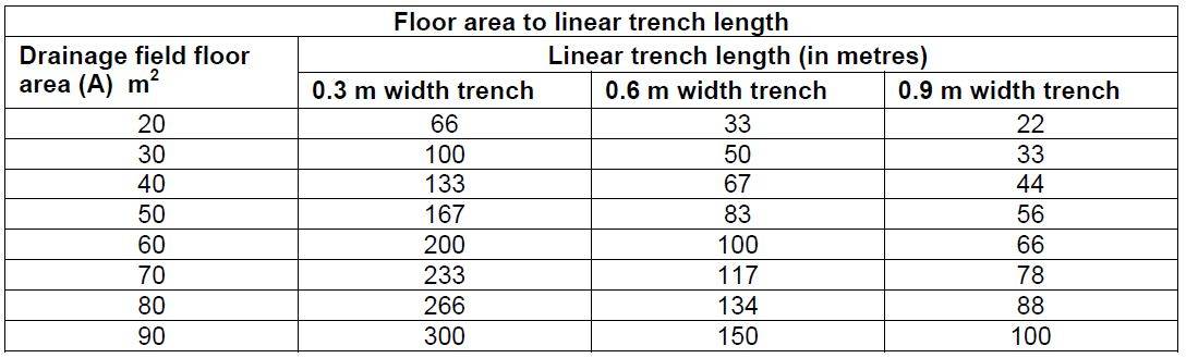
The calculated area A should be converted to an amount of linear trench based on the width of the trench which is usually between 0.3 m to 0.9 m. The layout of the trench network will depend upon the soil porosity and the availability of land but the legs of the trenches should be connected so as to form complete loops.
Where the calculated result indicates the need for a long drainage trench length (200 metes) serious consideration should be given to the use of a package treatment system which has been certified to produce a better quality of effluent. This effluent may, with permission, be fed into a water course or open culvert. Please contact us for further details. All equipment (for less than <50 pop equivalent) should meet the requirements of their relevant standard, i.e. EN 12566 part 1 for septic tanks, or EN 12566 part 3 for package treatment plants.
Effluent processed through a treatment plant contains far fewer pollutants and fine solids than that from a septic tank. Therefore the irrigation system is better protected and less likely to block and is smaller. The standard recognizes this fact and differentiates. As an example: Irrigation systems for domestic applications
In all cases treated effluent:
- will have a lower long term impact on the site as less pollutants are discharged
- will generate fewer solids thus preserving the life of the irrigation system
- requires a smaller irrigation system which is less expensive to install & easier to locate on a restricted or poorly draining site.
How To Design An Irrigation System
Your recommended certified Installer should be consulted regarding the design and fabric of the drainage field for your specific site. BS 6297: 2007 provides detailed design and installation advice and advises of features influencing the position of wastewater treatment equipment and drainage fields. e.g. not closer than 7m to a building. Drainage fields should be a minimum of 10 m away from a water course or ditch. 2m away form site boundaries, away from trees and plants with extensive root systems, and from existing supply services, access roads and other drainage fields. The detailed preliminary assessment should have identified other limiting criteria such as water abstraction areas, a Site of Special Scientific Interest (SSS) etc.
In brief, after the septic tank or treatment unit, the effluent pipe should be connected to an inspection &/or distribution chamber which leads to the drainage field. This should be designed as a closed circuit with facilities for inspection and maintenance. The layout should ensure even distribution throughout the absorption field, avoiding steep gradients on sloping sites. An inspection chamber at the furthest point from entry on each leg or loop is advisable.
The drainage / sub-surface irrigation system should be very carefully constructed using 110 mm downward facing perforated pipes laid in trenches with a uniform gradient not steeper than 1:200. The trenches should be between 300mm and 900 mm wide and minimum 1m wide strips of undisturbed ground should be maintained between parallel trenches. The pipes should be laid on a 200- 300 mm layer of clean gravel granular fill material graded either 16-32mm or 20-50mm. The trenches should be filled with the same material to a level 50mm above the pipe and covered with geotextile material to prevent the entry of silt. The remainder of the trench can be filled with normal soil. Pipes should be laid at a minimum depth of 200mm below the surface. Corrugated pipes designed specifically for land drainage should not be used.